CRLH Parameter Extraction
Setup a composite-right/left-handed (CRLH) unit cell and extract the equivalent circuit parameter.
Introduction
This tutorial covers:
Setup a feeding mircostrip line & port
Apply an inhomogeneous mesh used for improved accuracy and simulation speed
Use an internal clss to setup a CRLH unit cell
Use the port voltages and currents to extract the unit cell equivalent circuit parameter
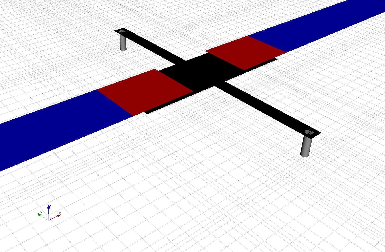
CRLH unit cell with feeding MSL.
Python Script
Get the latest version from git.
Import Libraries
import os, tempfile
from pylab import *

from CSXCAD  import ContinuousStructure
from openEMS import openEMS
from openEMS.physical_constants import *
Class to represent single CRLH unit cells
class CRLH_Cells:
    def __init__(self, LL, LW, Top, Bot, GLT, GLB, SL, SW, VR):
        self.LL  = LL   # Line length
        self.LW  = LW   # Line width
        self.Top = Top  # top signal height
        self.Bot = Bot  # bottom signal height
        self.GLT = GLT  # gap length top
        self.GLB = GLB  # gap length bottom
        self.SL  = SL   # stub length
        self.SW  = SW   # stub width
        self.VR  = VR   # via radius
        self.props = dict() # property dictionary
        self.edge_resolution = None

    def createProperties(self, CSX):
        for p in ['metal_top', 'metal_bot', 'via']:
            self.props[p] = CSX.AddMetal(p)

    def setEdgeResolution(self, res):
        self.edge_resolution = res

    def createCell(self, translate = [0,0,0]):
        mesh = [[],[],None]
        third_res = self.edge_resolution/3
        translate = array(translate)
        start = [-self.LL/2 , -self.LW/2, self.Top] + translate
        stop  = [-self.GLT/2,  self.LW/2, self.Top] + translate
        box = self.props['metal_top'].AddBox(start, stop, priority=10)
        # create edge mesh at +x and -+y
        mesh[0] += [stop[0]-third_res, stop[0]+2*third_res]
        mesh[1] += [stop[1]-third_res, stop[1]+2*third_res]
        mesh[1] += [start[1]-2*third_res, start[1]+third_res]


        start = [+self.LL/2 , -self.LW/2, self.Top] + translate
        stop  = [+self.GLT/2,  self.LW/2, self.Top] + translate
        box = self.props['metal_top'].AddBox(start, stop, priority=10)
        # create edge mesh at -x
        mesh[0] += [stop[0]-2*third_res, stop[0]+third_res]

        start = [-(self.LL-self.GLB)/2, -self.LW/2, self.Bot] + translate
        stop  = [+(self.LL-self.GLB)/2,  self.LW/2, self.Bot] + translate
        box = self.props['metal_bot'].AddBox(start, stop, priority=10)
        # create edge mesh at -+x
        mesh[0] += [start[0]+third_res, start[0]-2*third_res]
        mesh[0] += [stop[0]-third_res, stop[0]+2*third_res]

        start = [-self.SW/2, -self.LW/2-self.SL, self.Bot] + translate
        stop  = [+self.SW/2,  self.LW/2+self.SL, self.Bot] + translate
        box = self.props['metal_bot'].AddBox(start, stop, priority=10)
        # create edge mesh at -+x and -+y
        mesh[0] += [start[0]+third_res, start[0]-2*third_res]
        mesh[0] += [stop[0]-third_res, stop[0]+2*third_res]
        mesh[1] += [start[1]+third_res, start[1]-2*third_res]
        mesh[1] += [stop[1]-third_res, stop[1]+2*third_res]

        start = [0, -self.LW/2-self.SL+self.SW/2, 0       ] + translate
        stop  = [0, -self.LW/2-self.SL+self.SW/2, self.Bot] + translate

        self.props['via'].AddCylinder(start, stop, radius=self.VR, priority=10)

        start[1] *= -1
        stop [1] *= -1
        self.props['via'].AddCylinder(start, stop, radius=self.VR, priority=10)

        return mesh


if __name__ == '__main__':
    ### Setup the simulation
    Sim_Path = os.path.join(tempfile.gettempdir(), 'CRLH_Extraction')
    post_proc_only = False

    unit = 1e-6 # specify everything in um

    feed_length = 30000

    substrate_thickness = [1524, 101 , 254 ]
    substrate_epsr      = [3.48, 3.48, 3.48]

    CRLH = CRLH_Cells(LL  = 14e3, LW  = 4e3, GLB = 1950, GLT = 4700, SL  = 7800, SW  = 1000, VR  = 250 , \
                      Top = sum(substrate_thickness), \
                      Bot = sum(substrate_thickness[:-1]))

    # frequency range of interest
    f_start = 0.8e9
    f_stop  = 6e9

    ### Setup FDTD parameters & excitation function
    CSX  = ContinuousStructure()
    FDTD = openEMS(EndCriteria=1e-5)
    FDTD.SetCSX(CSX)
    mesh = CSX.GetGrid()
    mesh.SetDeltaUnit(unit)

    CRLH.createProperties(CSX)

    FDTD.SetGaussExcite((f_start+f_stop)/2, (f_stop-f_start)/2 )
    BC   = {'PML_8' 'PML_8' 'MUR' 'MUR' 'PEC' 'PML_8'}
    FDTD.SetBoundaryCond( ['PML_8', 'PML_8', 'MUR', 'MUR', 'PEC', 'PML_8'] )

    ### Setup a basic mesh and create the CRLH unit cell
    resolution = C0/(f_stop*sqrt(max(substrate_epsr)))/unit /30 # resolution of lambda/30
    CRLH.setEdgeResolution(resolution/4)

    mesh.SetLines('x', [-feed_length-CRLH.LL/2, 0, feed_length+CRLH.LL/2])
    mesh.SetLines('y', [-30000, 0, 30000])

    substratelines = cumsum(substrate_thickness)
    mesh.SetLines('z', [0, 20000])
    mesh.AddLine('z', cumsum(substrate_thickness))
    mesh.AddLine('z', linspace(substratelines[-2],substratelines[-1],4))

    # create the CRLH unit cell (will define additional fixed mesh lines)
    mesh_hint = CRLH.createCell()
    mesh.AddLine('x', mesh_hint[0])
    mesh.AddLine('y', mesh_hint[1])

    # Smooth the given mesh
    mesh.SmoothMeshLines('all', resolution, 1.2)

    ### Setup the substrate layer
    substratelines = [0] + substratelines.tolist()
    start, stop = mesh.GetSimArea()

    for n in range(len(substrate_thickness)):
        sub = CSX.AddMaterial( 'substrate_{}'.format(n), epsilon=substrate_epsr[n] )
        start[2] = substratelines[n]
        stop [2] = substratelines[n+1]

        sub.AddBox( start, stop )

    ### Add the feeding MSL ports
    pec = CSX.AddMetal( 'PEC' )
    port = [None, None]
    x_lines = mesh.GetLines('x')
    portstart = [ x_lines[0], -CRLH.LW/2, substratelines[-1]]
    portstop  = [ -CRLH.LL/2,  CRLH.LW/2, 0]
    port[0] = FDTD.AddMSLPort( 1,  pec, portstart, portstop, 'x', 'z', excite=-1, FeedShift=10*resolution, MeasPlaneShift=feed_length/2, priority=10)


    portstart = [ x_lines[-1], -CRLH.LW/2, substratelines[-1]]
    portstop  = [ +CRLH.LL/2 ,  CRLH.LW/2, 0]
    port[1] = FDTD.AddMSLPort( 2,  pec, portstart, portstop, 'x', 'z', MeasPlaneShift=feed_length/2, priority=10)

    ### Run the simulation
    if 1:  # debugging only
        CSX_file = os.path.join(Sim_Path, 'CRLH_Extraction.xml')
        if not os.path.exists(Sim_Path):
            os.mkdir(Sim_Path)
        CSX.Write2XML(CSX_file)
        from CSXCAD import AppCSXCAD_BIN
        os.system(AppCSXCAD_BIN + ' "{}"'.format(CSX_file))

    if not post_proc_only:
        FDTD.Run(Sim_Path, cleanup=True)

    ### Post-Processing
    f = linspace( f_start, f_stop, 1601 )
    for p in port:
        p.CalcPort( Sim_Path, f, ref_impedance = 50, ref_plane_shift = feed_length)

    # calculate and plot scattering parameter
    s11 = port[0].uf_ref / port[0].uf_inc
    s21 = port[1].uf_ref / port[0].uf_inc

    plot(f/1e9,20*log10(abs(s11)),'k-' , linewidth=2, label='$S_{11}$')
    plot(f/1e9,20*log10(abs(s21)),'r--', linewidth=2, label='$S_{21}$')
    grid()
    legend(loc=3)
    ylabel('S-Parameter (dB)')
    xlabel('frequency (GHz)')
    ylim([-40, 2])

    ### Extract CRLH parameter form ABCD matrix
    A = ((1+s11)*(1-s11) + s21*s21)/(2*s21)
    C = ((1-s11)*(1-s11) - s21*s21)/(2*s21) / port[1].Z_ref

    Y = C
    Z = 2*(A-1)/C

    iZ = imag(Z)
    iY = imag(Y)

    fse = interp(0, iZ, f)
    fsh = interp(0, iY, f)

    df = f[1]-f[0]
    fse_idx = np.where(f>fse)[0][0]
    fsh_idx = np.where(f>fsh)[0][0]

    LR = 0.5*(iZ[fse_idx]-iZ[fse_idx-1])/(2*pi*df)
    CL = 1/(2*pi*fse)**2/LR

    CR = 0.5*(iY[fsh_idx]-iY[fsh_idx-1])/(2*pi*df)
    LL = 1/(2*pi*fsh)**2/CR

    print(' Series tank: CL = {:.2f} pF,  LR = {:.2f} nH -> f_se = {:.2f} GHz '.format(CL*1e12, LR*1e9, fse*1e-9))
    print(' Shunt  tank: CR = {:.2f} pF,  LL = {:.2f} nH -> f_sh = {:.2f} GHz '.format(CR*1e12, LL*1e9, fsh*1e-9))

    ### Calculate analytical wave-number of an inf-array of cells
    w = 2*pi*f
    wse = 2*pi*fse
    wsh = 2*pi*fsh
    beta_calc = real(arccos(1-(w**2-wse**2)*(w**2-wsh**2)/(2*w**2/CR/LR)))

    # plot
    figure()
    beta = -angle(s21)/CRLH.LL/unit
    plot(abs(beta)*CRLH.LL*unit/pi,f*1e-9,'k-', linewidth=2, label=r'$\beta_{CRLH,\ 1\ cell}$' )
    grid()
    plot(beta_calc/pi,f*1e-9,'c--', linewidth=2, label=r'$\beta_{CRLH,\ \infty\ cells}$')
    plot(real(port[1].beta)*CRLH.LL*unit/pi,f*1e-9,'g-', linewidth=2, label=r'$\beta_{MSL}$')
    ylim([1, 6])
    xlabel(r'$|\beta| p / \pi$')
    ylabel('frequency (GHz)')
    legend(loc=2)

    show()
Images
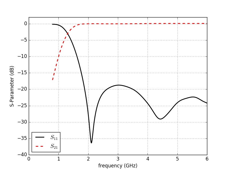
CRLH cell S-parameter
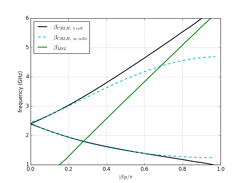
CRLH unit cell dispersion diagram